As the proliferation of video recordings increase, it is becoming more readily available in major incident and collision investigations. This growth creates significant value to investigators but it can be very important to understand the details of the recording.
Accident reconstructionists want to measure distance and timing for the purpose of calculating speeds of vehicles, especially in pre-impact conditions where no physical evidence is available on the scene. It may also be useful to the analyst trying to determine the position of objects or actions of persons or the relationship to each other in major incident investigations.
However, the frame rate of video recordings, particularly but not exclusively from CCTV systems, are not always what they purport to be. Timing is often inaccurate; frame rates are often misidentified and misleading and the method of counting frames and assuming a consistent frame rate will have led many investigators to produce inaccurate measurements.
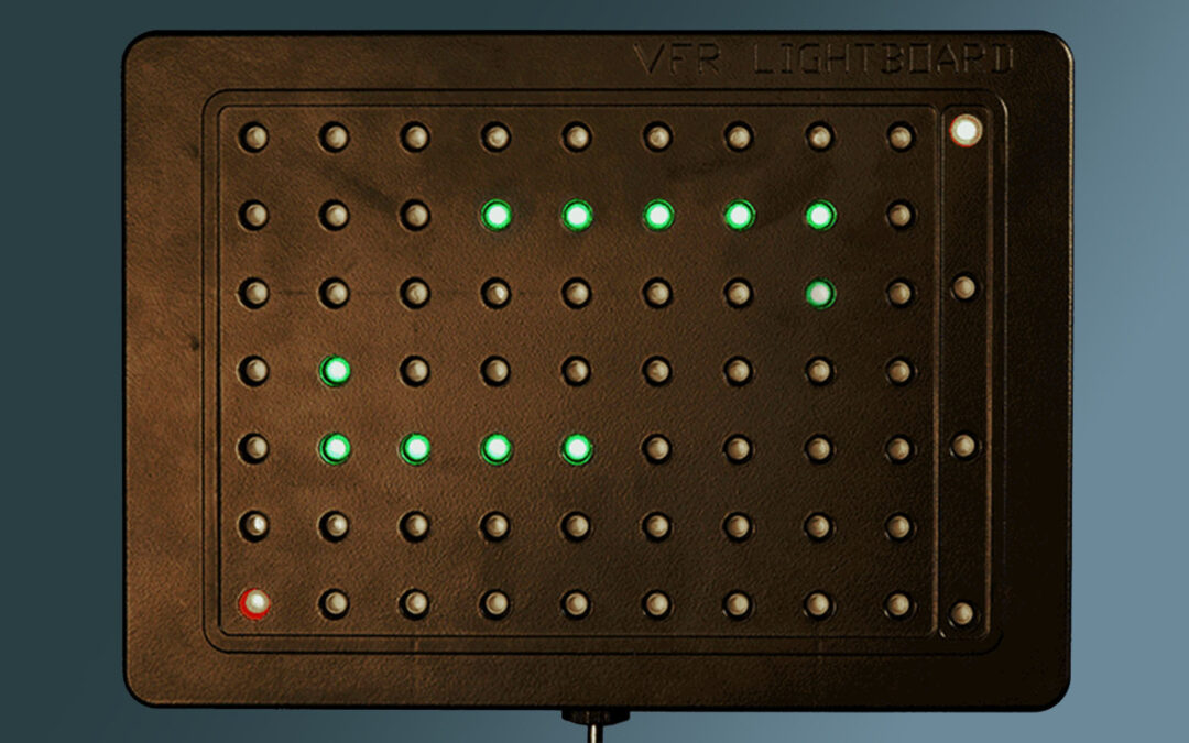
The new Variable Frame Rate (VFR) Lightboard provides an easy workflow to provide the elapsed time element for vehicle speed calculations within a reported margin of error.
If you are already familiar with previously available lightboards you will appreciate knowing that this unit weighs less than 1 kg!
How does the VFR Lightboard work?
Processing the new recording.
To process the recording you will need a copy of iNPUT-ACE with the VFR Lightboard Calculator add-on activated. The VFR Lightboard Calculator can be accessed via the Tools tab in iNPUT-ACE. - The LEDs on the board are illuminated in a set pattern, the VFR Lightboard Calculator automatically identifies which LEDs are illuminated on every frame.
However, due to the significant differences in recording environments and recording devices, these automatic detections must be manually validated to ensure that the final calculation is accurate. This manual validation process must be performed on every frame in the sequence. This sounds onerous until you try it and see how quickly you can process 400+ frames and compared to a manual reading approach it is a breeze.
Precisely defined margin of error
Once processed the minimum and maximum elapsed time for a given number of frame intervals is presented in an Image Timing Report pdf. Analysts also have the option to obtain a spreadsheet of all the data gleaned from the recording of the lightboard.
Timing between frames

extract from pdf report showing Min/Max for a 10 frame interval

Sample spreadsheet
More detailed information is available in the iNPUT-ACE User Manual.
What next?
So now you have the time element of the speed calculation formula. There are various ways to get the Distance element, one being using reverse projection. The iNPUT-ACE Camera Match Overlay tool provides an excellent method to produce a distance calculation from the same surveillance video and a 3D scan of the locus, making iNPUT-ACE an end-to-end solution for calculating timing and distance for speed calculation.